Jig:An Experiment in AI-Built CAD Parts for OpenUSD, Without an RTX Card
Nov 9, 2026 · 9 min read
Jig is a private project I'm building with Claude Code while exploring OpenUSD. From a sentence, it builds exact, parametric CAD parts on an ordinary computer, checks them as line drawings, and writes OpenUSD files that open in NVIDIA Omniverse, alongside STEP, STL and 3MF files for manufacturing.
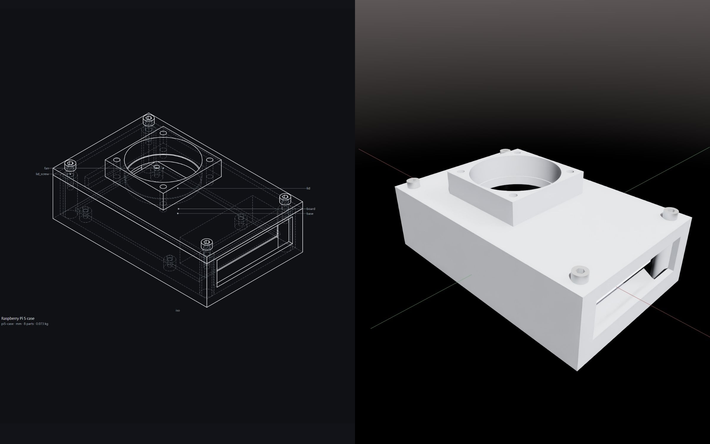
Jig grew out of two earlier projects. My DSX POD site simulator was a three-day project. Its equipment models were made by talking to AI, and the site exported to OpenUSD with each piece kept as a reference, so it opened in NVIDIA Omniverse as one scene made of separate components.
After that, I spent about a week building Plinth, a tool that keeps a digital product's design tokens and voice in code. Programs compute what they can, AI drafts and I confirm, and checks run on every change.
So I wondered whether 3D assets could work the same way: described in a form AI can read and help build, with the same kind of checks. There was a practical reason too. OpenUSD itself is an open file format, but Omniverse's apps need an NVIDIA RTX graphics card, so whenever I worked on the simulator, I was remoting from my Mac into a desktop PC through RustDesk. I wanted to do the modeling on the Mac itself.
If I only want to make and check one component before it goes into a scene, a bracket, a case or a container, do I need that card at all? Could AI build the part as CAD, check it through line drawings, and hand over a USD file that Omniverse can open?
Jig is my experiment to find out. There are already tools exploring AI-assisted CAD. Building my own was the fastest way for me to understand how the pieces fit together. It's a private project, so this post shows the approach and a recorded run rather than the code.
Key points
- Modeling without an RTX card: Claude writes each part as a list of steps, a CAD kernel turns them into exact geometry on the CPU, and I check the result as line drawings.
- One model, several files: OpenUSD for Omniverse, STEP for other CAD software, and STL and 3MF for 3D printing.
- Guesses stay visible: when Claude has to assume a size, it stays marked until I confirm it.
From one sentence to a scene graph
- 1DescribeA sentence, a STEP file or a photo. If something is missing, Claude asks, with a default for each question.
- 2Find what existsParts to copy and edit: the standard catalog, my library, my other models.
Assets to reference: model libraries like SimReady, left as they are. - 3Scene graphI approveEvery part marked new, catalog or library. Nothing is built before I approve.
- 4SkeletonA placeholder box for each part, so the whole assembly is there from the start.
- 5DetailClaude writes each recipe, the CAD kernel computes it on the CPU, and Jig checks it. A failure goes back to Claude.
- 6Confirm sizesGuessed sizes stay marked until I confirm them.
- 7First versionSaved and editable: point at a part to change it, cut a section to look inside, export USD, STEP, STL and 3MF.
The run in the video started with one sentence:
A case for a Raspberry Pi 5: a base and a lid, with a 30 mm fan on the lid.
A sentence is one way to start. An existing STEP file, say a vendor's model of a board or a motor, can come in too. Jig doesn't turn it into a parametric model. It keeps the file as it is and uses it as the first step of a part, so I can measure it, check the parts around it for fit, add holes or cuts as new steps, and send it out as a USD component like any other part. If the vendor updates the file, the part is marked to rebuild from the new version. A mesh such as an STL can't be cut, so it comes in as a reference instead. I've started on photos and sketches too, but so far I've only tried rendered images, not real photos from a phone.
Claude doesn't start drawing right away. It first looks for parts that already exist: my own library, my other models, a small catalog of standard parts, and NVIDIA's SimReady assets online. Here, it found a standard M3 screw but nothing for the board or the fan, so it proposed four new parts and showed the case as a scene graph. Nothing gets built until I approve the plan.
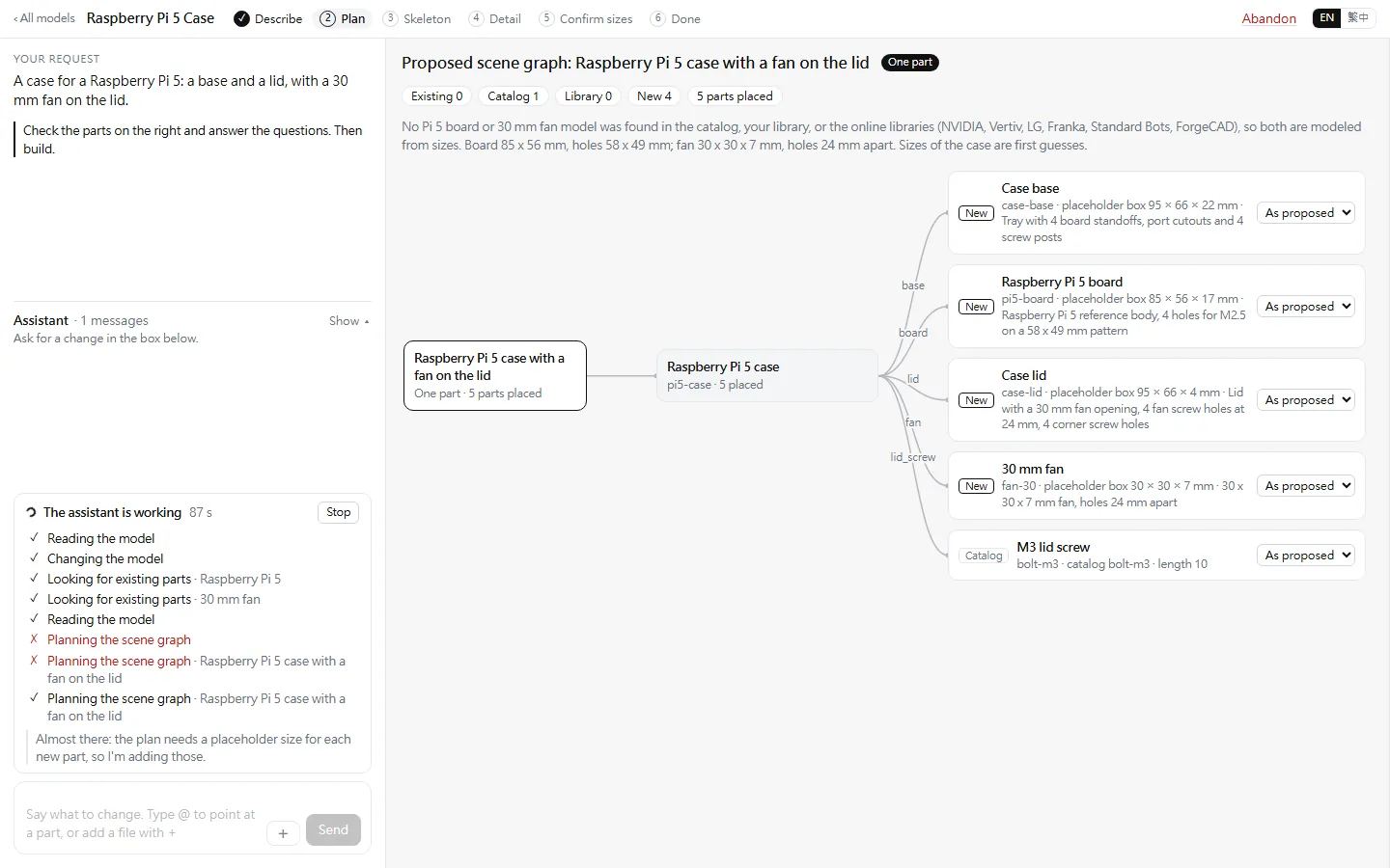
After I approve, Jig puts a placeholder box where each part goes, and Claude details the parts one by one. Each part is a recipe, a list of steps like sketch, extrude, cut and fillet, with every size named so it can be changed later. Claude writes the recipe, and a CAD kernel (build123d, built on the open-source OpenCascade) computes the shape. If a step fails, Jig tells Claude why, and Claude tries again.
Some sizes have to be guessed, like the fan's thickness or the spacing of its screw holes. Those stay marked in amber until I confirm them. The shape is exact, but it's only as right as the sizes behind it, and I'd rather see the guesses than have them hidden. In this run, I accepted them all and saved the first version about four minutes after sending the sentence.
Checking the part in line drawings
Jig draws every part from the top, front and side, plus a 3D view, with hidden edges dashed and dimensions measured from the shape. I use these drawings to check sizes, holes and whether things fit. Jig also checks whether parts overlap and works out the weight.
These are simple geometry checks, not engineering analysis. They can't tell me whether a screw will hold or a wall is strong enough. All of them run on the CPU, and the drawings are SVG files any browser can show.
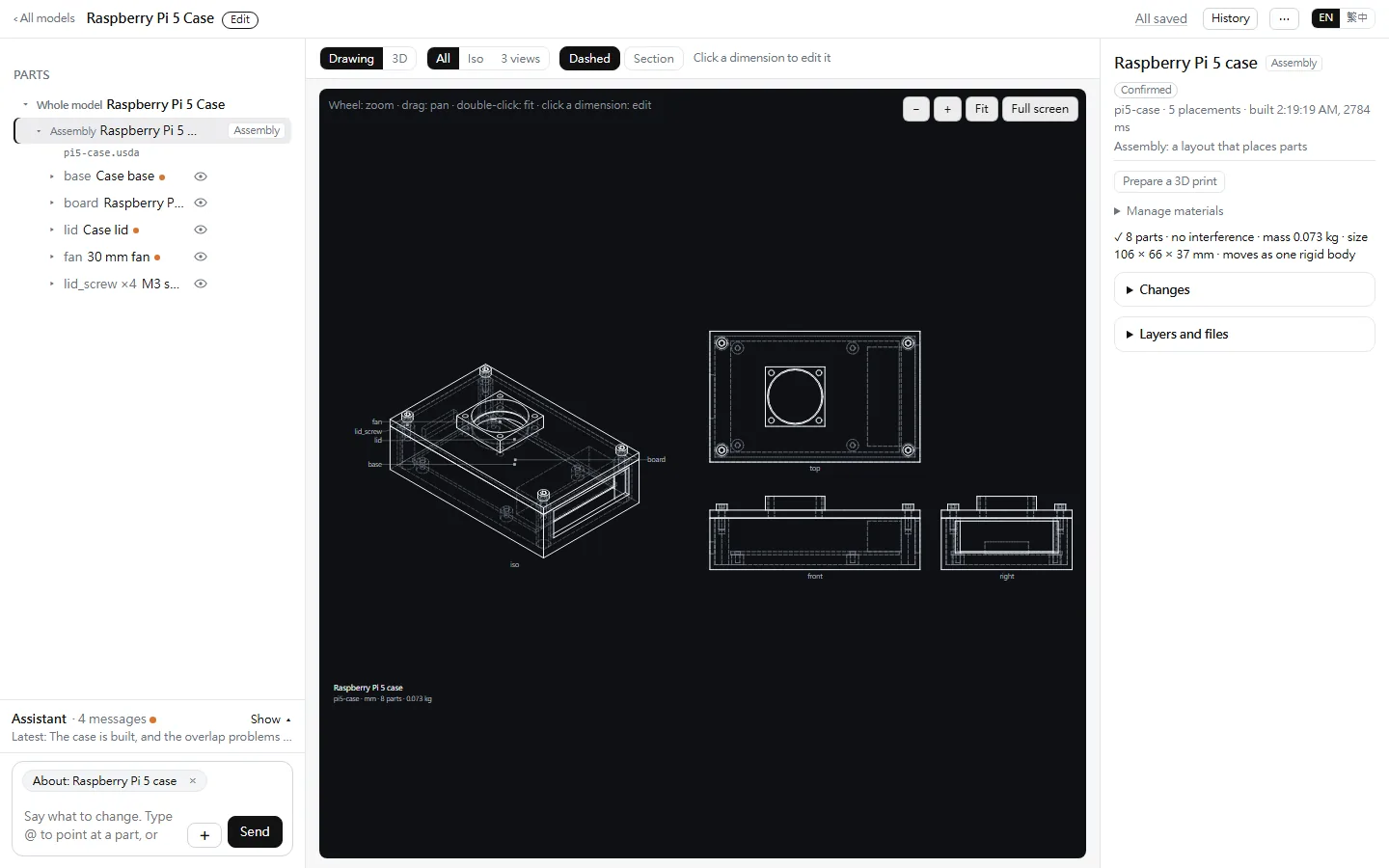
Looking doesn't change the model. A section cut or another view is only drawn on the page, so I can look around freely without leaving anything to save.
To change something, I start from the part. I typed @, picked the fan, and wrote:
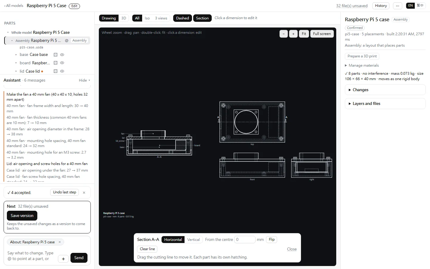
Change @fan to a 40 mm fan.
Claude changed the fan and updated the lid to match: the opening grew from 27 to 37 mm, and the screw holes moved from 24 to 32 mm apart. It listed each change with old and new values, and marked new guesses again.
Of the six minutes, Claude Code spent 221 seconds working on my three requests, about US$0.84 at API prices. On my Claude Code subscription, it counts toward the usage limit instead. The rest of the time was me reading the plan, confirming sizes and cutting the section.
Claude Code in the background, the result in the Claude app
Jig doesn't call a model API itself. Its page passes each request to Claude Code running in the background, with Jig's tools loaded as a plugin. That lets me use Claude's newer models and its general engineering knowledge without building an AI agent of my own.
That knowledge matters. Someone without mechanical CAD training can ask how two parts should connect, and Claude can build a few options to compare. The trade-off is that Jig depends on Claude Code, and each run uses part of my usage limit.
Jig also writes a self-contained 3D page for each model, which opens as an artifact in the Claude app. On my phone, I can turn the case with one finger, pinch to zoom, tap a part to see its name, and ask for changes in the conversation.
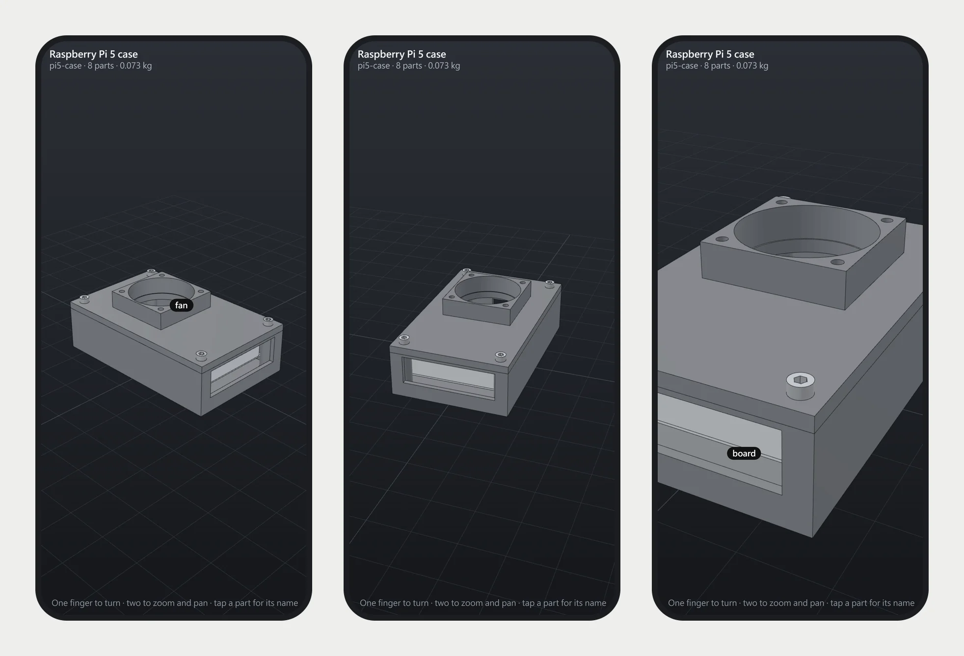
I can also run the whole thing from my phone. Through the Claude app, I talk to a Claude Code session on my desktop; it hands the request to Jig, and the result comes back as an artifact. A simple plate took under a minute from the sentence to its first saved version.
Into Omniverse
For each part, Jig writes a USD file with materials, labels and basic physics properties like mass, and an assembly points to its parts instead of copying them.
That matters most when something has to change. An OpenUSD scene can reference many separate models. Changing one of them usually means going back to the CAD software, editing it, exporting and converting it again, and then doing the same for the next model. I imagine that adds up quickly in a scene with many models.
In Jig, I ask for the change in a sentence, at my desk or from my phone. Claude changes the part and the parts that have to follow, the checks run again, and Jig rewrites the same USD file. A scene that references that file picks up the new version the next time it loads, without the scene itself being touched.
I opened the files in Omniverse to see whether they hold up. They load in USD Composer and pass the Asset Validator, apart from one rule about file format, and in a simple physics test the case drops and settles as one body. That's as far as my simulation testing goes so far.
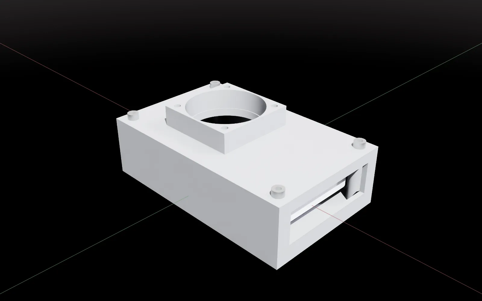
The same model also exports STEP for other CAD software, and STL and 3MF for 3D printing.
For equipment that already exists, a library makes more sense than modeling it again. NVIDIA and Vertiv publish SimReady assets on Hugging Face, and Jig brings them in as references without changing the original files.
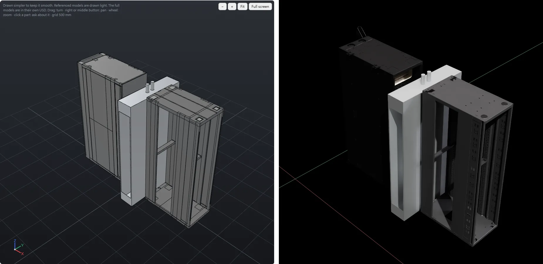
Some of these assets are heavy: NVIDIA's GB300 rack has nearly 25 million triangles. So Jig shows a much lighter version in its own view, and gets simpler still when the computer can't keep up.
Jig models components, not factory layouts
Where a fan sits on a case lid is part of modeling the case. Where that case, a rack or a machine goes in a factory feels like a different job, and in USD it seems to belong to whoever builds the scene. Jig can place parts together to check that they fit, but I don't think factory layout should be its job. I'm curious how teams split this work in practice.
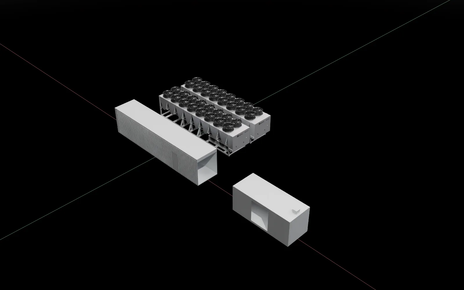
To test the reason I started this, I built a container data center in Jig on my Mac, an older Intel MacBook Pro without an NVIDIA card. It's based on the GIGABYTE GADU from the same site simulator project. Jig modeled the container, power skid and cooler, and the chillers and racks came from SimReady libraries.
Closing the loop: two ideas I haven't built
Model, simulate, adjust
Claude models a part, Omniverse tests it in simulation, and the results come back to Jig for another round. For now it's a sketch of a workflow, not a plan.
- What exists: USD files with basic physics that open in Omniverse.
- What's missing: reading results back, knowing when to stop, and deciding where I approve each round.
Print, measure, adjust
A 3D printer makes the part, and from photos, temperatures and the part's weight, Claude suggests how the model should change.
- What exists: a print record for each part, and print time and filament estimates from OrcaSlicer.
- What's missing: a connection to the printer, a camera, and the printer itself.
What's next
A printer
I don't own a 3D printer yet. Getting one to try the second loop would be a good next step.
Beyond Claude Code
I'd also like to separate Jig from Claude. Its tools already use MCP, an open protocol other agents can use too. What ties Jig to Claude is mainly how its page starts Claude Code. Opening that up could let people choose their own agent, including a model running on their own computer, so a confidential part never has to leave the machine. A smaller local model would likely make more mistakes, and I'm curious how far the checks can carry it.
One model or two?
The question I keep coming back to is whether simulation and manufacturing should share one model. A model for an Omniverse production line needs looks, labels, physics and light files. A model for making something, whether by 3D printing, CNC or sheet metal, needs exact sizes, tolerances and drawings.
The checks differ too: can the walls be printed, can a cutter reach the corners, can the sheet be bent. Jig has a few of the 3D printing checks, such as walls that are too thin and overhangs that need support. CNC and sheet metal have none yet.
My current guess is one model with two exits: the same parametric part, with different outputs and checks for simulation and for manufacturing. Both loops above come back to the same model, which is part of why I lean this way. People who work in simulation or manufacturing every day may see it differently, and I'd like to hear how. It's still an open question for me.
Where it stands
Jig is a proof of concept. I built it in about three days, right after finishing Plinth. It runs on Windows and macOS with Claude Code and has 176 automated tests. I'm its only user so far, and it isn't open source.
Outcome: a sentence to an exact parametric part on an ordinary computer, with existing STEP files as fixed parts to build on; line drawings and simple geometry checks; USD files with materials, labels and basic physics that open in USD Composer; and STEP, STL and 3MF files for making the part.
So, back to the question I started with. For making and checking a component, I didn't need an RTX card, and the Mac was enough for the modeling. The card came in only at the end, when I opened the case in Omniverse to render it.
The next step is finding out how much of this holds up in a real digital twin project.